GINA
- OpenWSN Admin
- David Burnett
- Thomas Watteyne
- Fabien Chraim
GINA (Guidance and Inertial Navigation Assistant) is a board developed developed through the WARPwING project in Prof. Kris Pister's lab. It combine a traditional "mote" (MSP430 microcontroller and AT86RF231 low-power radio) with several inertial sensors (acceleration, magnetometer, gyroscope). It is used as a "control unit" of un-maned vehicles.
OpenWSN support
GINA is fully supported in OpenWSN.
The OpenWSN builders build the GINA firmware nightly:

Ecosystem
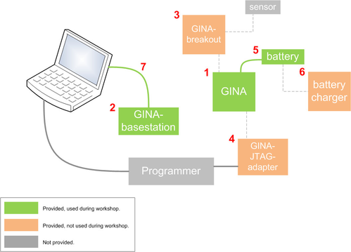
The Guidance and Inertial Navigation Assistant developed through the WARPwING project in Prof. Kris Pister's lab. The diagram below presents the GINA ecosystem.
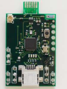
GINA
The Guidance and Inertial Navigation Assistant (GINA) platform is a low-power wireless mote augmented with inertial measurement capabilities.
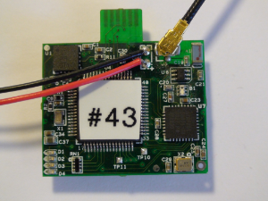
It features:
type | manufacturer | part/datasheet | details | vendor | |
U4 | microcontroller | 16-bit, 16MHz, 116kB flash, 8kB RAM | |||
U7 | radio | IEEE802.15.4-compliant, 2Mbps-capable | |||
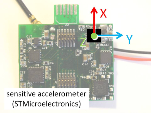
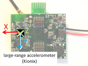
U1 | 3-axis accelerometer (sensitive) | +/-2 Gs or +/-6 Gs, 1.8 kHz, 660 mV/G, 50 uG/rtHz | |||
U8 | 3-axis accelerometer (large range) | +/-8 Gs, 2 kHz | |||
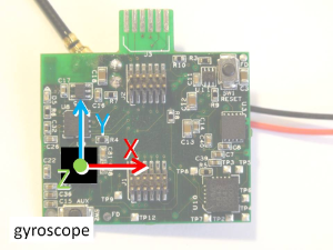
U9 | 3-axis gyroscope | 2000 degs/s | |||
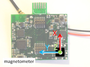
U10 | 3-axis magnetometer | compass | |||
U11 | temperature sensor | +/-2.5 C, -55 C to 130 C | |||
A1 | antenna (chip) | 2.4GHz | |||
J5 | antenna (connector) | microcoaxial | |||
J1,J2 | expansion headers | 12 pin, 2x6, 0.8 mm pitch, brd-brd male hdr | |||
D1,D2,D3,D4 | user LEDs | different, see bill of materials | yellow, green, orange, red | ||
J3 | JTAG port (traces on board) | N.A. | N.A. | connects to the GINA-JTAG-adapter | N.A. |
SW1, SW2 | reset, auxiliary buttons | momentary switch |
The orientation of the axes of the inertial sensors are:
It has been:
- designed by the Kris Pister group at UC Berkeley;
- fabricated by Boardworks (12 mils thick, 4 layers, Pb-free HASL plating);
- assembled by Digicom Electronics.
All of the information about this open-source board can be found at http://warpwing.sourceforge.net/, including:
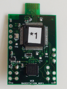
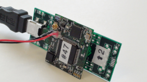
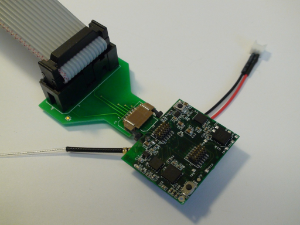
GINA-basestation
This board is a stripped-down version of the GINA above. It's only a communicating board, i.e. it has no inertial measurement capabilities. Instead, it features a UART-to-USB bridge chip and a mini-B USB connector.
type | manufacturer | part/datasheet | details | vendor | |
U1 | microcontroller | 16-bit, 16MHz, 116kB flash, 8kB RAM | |||
U4 | radio | IEEE802.15.4-compliant, 2Mbps-capable | |||
A1 | antenna (chip) | 2.4GHz | |||
J3 | USB connector | UX60A-MB-5ST | Type B, receptacle, female contacts, surface mount, right angle | ||
U5 | UART-to-USB bridge | 28-pin, slave USB interface, QFN-28 | |||
J1 | JTAG port (traces on board) | N.A. | N.A. | connects to the GINA-JTAG-adapter | N.A. |
It has been:
- designed by the Kris Pister group at UC Berkeley;
- fabricated by Boardworks;
- assembled by Digicom Electronics.
All of the information about this open-source board can be found at http://warpwing.sourceforge.net/, including:
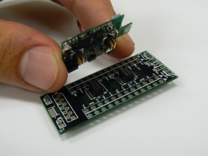
GINA-breakout
This breakout card is used as a practical way of connecting external sensors to the header pins of the GINA platform.
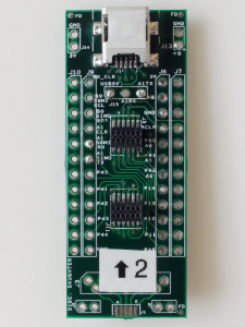
It features:
type | manufacturer | part/datasheet | details | vendor | |
J3 | USB connector | UX60A-MB-5ST | Type B, receptacle, female contacts, surface mount, right angle | ||
J5,J11 | expansion headers | 12 pin, 2x6, 0.8 mm pitch, brd-brd male hdr | |||
U1 | UART-to-USB bridge | 28-pin, slave USB interface, QFN-28 |
It has been:
- designed by the Kris Pister group at UC Berkeley;
- fabricated by Boardworks;
- assembled by Digicom Electronics.
All of the information about this open-source board can be found at http://warpwing.sourceforge.net/, including:
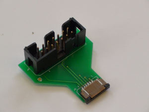
GINA-JTAG-adapter
This adapter card is used to reprogram the firmware on either the GINA or the basestation board. This adapter interfaces between the board and a TI JTAG debug adapter for the MSP430 MSP-FET430UIF.
It features:
type | manufacturer | part/datasheet | details | vendor | |
J2 | JTAG connector | 2514-6002RB | 14 pin, 2x7, 100 mil pitch, ribbon cable hdr, end shroud | ||
J1 | GINA connector | 6 pin, 1x6, 1 mm pitch female, top contact flex, right angle |
It has been:
- designed by the Kris Pister group at UC Berkeley;
- fabricated by Boardworks;
- assembled by Digicom Electronics.
All of the information about this open-source board can be found at http://warpwing.sourceforge.net/.
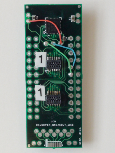
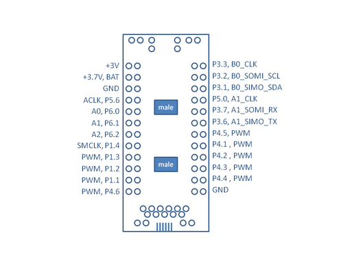
Breakout Daughtercard
You can use the breakout daughtercard to connect wires to the expansion headers of the GINA board.
This diagram shows, once connected, what the breakout board holes correspond to. The adjacent vertical rows along the left and right edges of the board are simply connected together for convenience, when you add your own wires.
Accessories
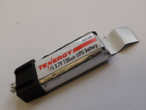
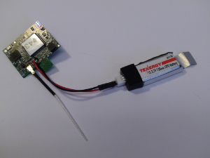
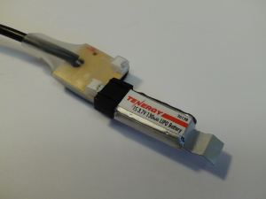
Battery
We use a lithium-polymer 3.7V 130mAh battery. It weighs 3.6 g and can be charged using the battery charger. It is manufactured by Tenergy as part# 39014. It can purchased from BSD Micro RC or Amazon.
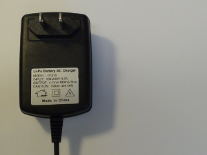
Battery Charger
It charges a battery in approx. 10 minutes, and can charge two batteries simultaneously. It can be purchased from All Battery or Amazon.
USB Cable
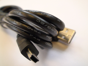
This is a Standard A male to Mini B male, 1m-long USB cable, used to connect a GINA-basestation mote to a computer. It can be purchased from Digikey.
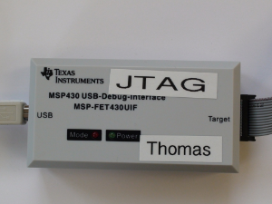
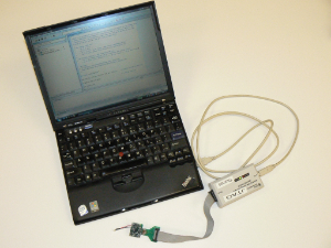
Programmer
The TI JTAG Debug Probe for the MSP430 MSP-FET430UIF is needed to reprogram the firmware on the GINA and GINA-Basestation boards, through the GINA JTAG Adapter Card.
- Make sure IAR is installed.
- Plug in the MSP-FET430UIF into a USB port.
- In most cases, the programmer will be recognized and drivers will be installed automatically.
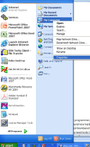
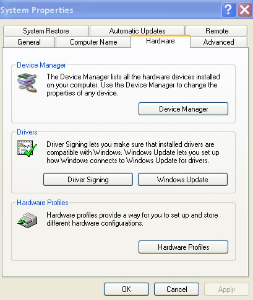
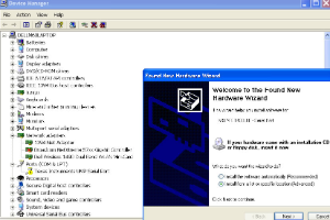
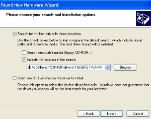
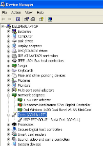
- If not, when Windows asks for a driver, point it to
C:\Program Files\IAR Systems\Embedded Workbench x.x\430\drivers\TIUSBFET\WinXP, or as appropriate for your version of Microsoft Windows. - If Microsoft Windows does not prompt for a driver, navigate down to the Device Manager and install it manually. Follow the screenshots below (click to enlarge). You may need to do this twice, once as a USB device and once as a serial device.
- Use the GINA JTAG Adapter Card to reprogram the GINA and GINA-Basestation boards.
Tools
Datasheets
Test Pads
There are 11 test pads on the GINA2.2 board. You can solder wires and use an oscilloscope to debug these signals which are internal to the board (i.e. are not
brought up to the daughtercard expansion headers).
- Use TP1 to ground your oscilloscope.
- Use TP7 and TP8 to eavesdrop on the I2C bus connecting the MSP430 to the gyroscope, 8G accelerometer and the magnetometer compass.
- Use TP9, TP10 and TP11 to eavesdrop on the SPI bus connecting the MSP430 to the radio.
TP1 | GND thru hole |
TP2 | Magnetometer DRDY |
TP3 | Magnetometer SVDD |
TP4 | Magnetometer OFFP |
TP5 | Magnetometer SETN |
TP6 | Magnetometer OFFN |
TP7 | B1_I2C_SCL (I2C) |
TP8 | B1_I2C_SDA (I2C) |
TP9 | A0_RF_SOMI (SPI) |
TP10 | A0_RF_SIMO (SPI) |
TP11 | A0_RF_SCLK (SPI) |
Stencil
You can download this board's stencil here.
Ordering Information
Digicom is the company which assembled the GINA2.2c boards designed by the Pister group. To order completely assembled GINA2.2c boards from them, follow these instructions prepared by Dr. Paul Samuel from Daedalus Flight Systems.
Specifically, the following elements are described.
- If needed, how to modify the Assembly Bill of Materials (BOM) for the GINA2.2c to reflect any components that should not be assembled;
- If needed, how to modify the Purchasing BOM for the GINA2.2c to reflect any components that should not be purchased by Digicom (either because they are not assembled, or because they are provided by you);
- Which files to send to Digicom;
- What information to include in the quote request.
Related content
