Sensor board and mote communication protocol (draft 8)
Introduction
The following document provides the necessary information for implementing a generic communication interface between the wireless board (mote) and the sensor board. Any kind of sensor board can be connected to the mote using this specification given it provides a SPI peripheral, one input pin with interrupt capability and one digital output. The sensor board must implement a special register set from which all required information can be retrieved.
![]() Code in under construction at this repository.
Code in under construction at this repository.
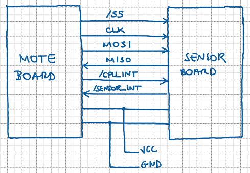
Pin out
New sensor boards can be seamless connected to a mote if the following characteristics are available:
- A sensor board with standard slave SPI channel SPI (MOSI, MISO, SCLK, /SS)
- Frequency of 4MHz for communication, using 8 bits, with with least significant bit (LSB) first
- Polarity and Phase clock must be set in mode 0 (both zero) .
Two interrupt lines are provided for indicating critical events. One line is from sensor to mote and the other is from mote to sensor.
- Sensor → mote interrupt line: When the mote wants to read values from the sensor it puts this line in high beforehand and waits 100ms. This signal is used to wake up the sensor from any possible energy saving mode, waiting for the communication. This line will be kept high while the mote continues to communicates with the sensor. If the sensor board does not provide any energy saving mode (always in active mode) or it can be activated quickly, this line can be ignored. In such situation, SPI chip select (/SS) will be used to detect the communication request.
- Processor → sensor interrupt line: This line is used for urgent notifications from sensor, indicating any asynchronous event that should be handled immediately . It may be an indication of an external event that can not wait for normal read cycle or a sensor failure, for instance. The mote will read the status register to acknowledge the interrupt, detecting the type of event, like a urgent point that should be read or some sensor failure. The sensor will deactivate this line only after the status register is read and a minimum time of 500ms should be respected before making this line active again.
Power supply lines are also provided (VCC and GND). In this case, the mote should be prepared to provide energy for the sensor board or to receive energy from it. Sensor boards that are capable of providing energy will indicate such situation in their identification registry (capability field).
Protocol Overview
The proposed protocol is based on several access to a register map defined in the sensor board. All accesses are synchronous so each request must be followed by a response and a maximum timeout need to be respected. Any communication frame can not be greater than 96 bytes (TBD). The exact amount of bytes is determined after reading the device identification register and point description registers. The idea is all sensor data fits inside a unique 6LoWPAN frame.
Data types used in this documentation are described in the data types table. There is no string data type and arrays should be considered as a regular array of any basic data type. When describing a field, numbers in front of the data type indicates the array size. For instance, 4L means a sequence of four unsigned longs (16 bytes). If the quantity is omitted it must be considered as 1. All data types that are longer than one byte should be considered as little endian.
The generic request frame is below:
| Size | Description |
|---|---|
| B | Frame Size (n+4 bytes) - CRC and size included |
| B | Register Address |
| nB | Frame Data (if any) |
| 2B | CRC |
Response frames are described below. All answers must be synchronous, with 500ms of timeout. After this timeout two retries can be done, with timeouts of 1000ms and 2000ms, respectively. If sensor board continues not responding, it should be considered in failure state and the mode should try to identify the board again at each one minute.
| Size | Description |
|---|---|
| B | Frame Size (n+5 bytes) - CRC and size included |
| B | Register Address |
| B | Response Status (see response code table) |
| nB | Frame Data |
| 2B | CRC |
CRC used is CRC16-ANSI (polynomial 0x8005, initial value 0xFFFF). This is the same algorithm used in other protocols like Modbus and a free implementation is available in FreeModbus project. CRC is calculated over header and payload (from size to last payload bye).
Sensor Board Register Map
The set of registers that should be implemented are listed below:
| Address | Access Rights | Description |
|---|---|---|
| 0x00 | RO | Sensor Board Interface Version |
| 0x01 | RO | Sensor Board Identification |
| 0x02 | RO | Sensor Board Status |
| 0x03 | WO | Sensor Board Command |
| 0x04 | RO | Read Battery Status |
| 0x05 | WO | Write Battery Status |
| 0x06 | RO | Read Battery Charge |
| 0x07 | WO | Write Battery Charge |
| 0x08 | WO | Wireless network status |
| 0x09 | WO | Wireless network Strength (RSSI, 0 to 100%) |
| 0x0A | WO | Display (when display is available) |
| 0x0B | RO | Main server address (IPv6) |
| 0x0C | RO | Secondary server address (IPv6) |
| 0x0D to 0x0F | -- | Reserved (Should not be answered) |
| 0x10 to 0x2F | RO | Sensor Point Description (Point 0 to 31) |
| 0x30 to 0x4F | RO | Read Sensor Point (Point 0 to 31) |
| 0x50 to 0x6F | WO | Write Sensor Point (Point 0 to 31) |
| 0x70 to 0xFF | -- | Reserved |
Command Description
Sensor Board Interface Version (0x00)
In this register is stored which version of the sensor interface is implemented. At this moment, only version available is 0x00 (alpha version).
Request
| Value | Size | Description |
|---|---|---|
| 0x04 | B | Size |
| 0x00 | B | Address |
| CRC | S | CRC |
Response
| Value | Size | Description |
|---|---|---|
| 0x06 | B | Size |
| 0x00 | B | Address |
| Status | B | Response status |
| Version | B | Interface version implemented |
| CRC | S | CRC |
Sensor Board Indentication (0x01)
This register returns the sensor identification, like serial number, name and the amount of sensor points available. The maximum number of sensor points is 32.
Request
| Value | Size | Description |
|---|---|---|
| 0x04 | B | Size |
| 0x01 | B | Address |
| CRC | S | CRC |
Response
| Value | Size | Description |
|---|---|---|
| 0x1C | B | Size |
| 0x01 | B | Address |
| Status | B | Response status |
| Model | 8B | Eight bytes describing the model name. This field may be filled with (0x00) |
| Manufacturer | 8B | Eight bytes describing the manufacture name. This field may be filled with (0x00) |
| ID | L | Sensor board ID |
| Revision | B | Hardware revision |
| Points | B | Number of points (maximum is 32 |
| Capabilities | B | Sensor capabilities (see capabilities table) |
| CRC | S | CRC |
Sensor Board Status (0x02)
This register holds the sensor board status, following table sensor status table. Critical and asynchronous events may be flagged using this register.
Request
| Value | Size | Description |
|---|---|---|
| 0x04 | B | Size |
| 0x02 | B | Address |
| CRC | S | CRC |
Response
| Value | Size | Description |
|---|---|---|
| 0x06 | B | Size |
| 0x02 | B | Address |
| Status | B | Response status |
| Status | B | Sensor Status Code |
| CRC | S | CRC |
Sensor Board Command (0x03)
A command can be sent to the sensor using this register. Refer to the command table (TDB).
Request
| Value | Size | Description |
|---|---|---|
| 0x05 | B | Size |
| 0x03 | B | Address |
| Command | B | Command |
| CRC | 2B | CRC |
Response
| Value | Size | Description |
|---|---|---|
| 0x06 | B | Size |
| 0x03 | B | Address |
| Status | B | Response status |
| Status | B | Command execution result |
| CRC | S | CRC |
Read Battery status (0x04)
If the power supply is provided by the sensor, it should report this information using the sensor capabilities field. In this case, this register is used to read the battery status. Please, refer to the battery status table.
Request
| Value | Size | Description |
|---|---|---|
| 0x01 | B | Size |
| 0x04 | B | Address |
| CRC | S | CRC |
Response
| Value | Size | Description |
|---|---|---|
| 0x03 | B | Size |
| 0x04 | B | Address |
| Status | B | Response status |
| Status | B | Battery status |
| CRC | S | CRC |
Write Battery status (0x05)
When the battery is attached to the mote, it can use this register to report battery information to the sensor board. A sensor board with display could show this information to the user.
Request
| Value | Size | Description |
|---|---|---|
| 0x05 | B | Size |
| 0x05 | B | Address |
| Status | B | Battery status |
| CRC | 2B | CRC |
Response
| Value | Size | Description |
|---|---|---|
| 0x05 | B | Size |
| 0x05 | B | Address |
| Status | B | Response status |
| CRC | 2B | CRC |
Read Battery charge (0x06)
If the power supply is provided by sensor it should report this information using the sensor capabilities field. In this case, this register is used to read the battery charge.
Request
| Value | Size | Description |
|---|---|---|
| 0x01 | B | Size |
| 0x06 | B | Address |
| CRC | S | CRC |
Response
| Value | Size | Description |
|---|---|---|
| 0x05 | B | Size |
| 0x06 | B | Address |
| Status | B | Response status |
| Charge | B | Battery charge (0 to 100%) |
| CRC | S | CRC |
Read Battery charge (0x07)
When the battery is attached to the mote, it can use this register to report battery charge to the sensor board. A sensor board with display could show this information to the user.
Request
| Value | Size | Description |
|---|---|---|
| 0x05 | B | Size |
| 0x07 | B | Address |
| Charge | B | Battery charge (0 to 100%) |
| CRC | 2B | CRC |
Response
| Value | Size | Description |
|---|---|---|
| 0x05 | B | Size |
| 0x07 | B | Address |
| Status | B | Response status |
| CRC | 2B | CRC |
Wireless network status (0x08)
This register is used to report the wireless status to the sensor board. A sensor board with display could show this information to the user. In this case, sensor capability should indicate that wireless information is required.
Request
| Value | Size | Description |
|---|---|---|
| 0x05 | B | Size |
| 0x08 | B | Address |
| Charge | B | Network status (see table) |
| CRC | 2B | CRC |
Response
| Value | Size | Description |
|---|---|---|
| 0x05 | B | Size |
| 0x08 | B | Address |
| Status | B | Response status |
| CRC | 2B | CRC |
Wireless network strength (0x09)
This register is used to report the wireless strength to the sensor board. A sensor board with display could show this information to the user. In this case, sensor capability should indicate that wireless information is required.
Request
| Value | Size | Description |
|---|---|---|
| 0x05 | B | Size |
| 0x09 | B | Address |
| Charge | B | Network signal strngth (0 to 100%) |
| CRC | 2B | CRC |
Response
| Value | Size | Description |
|---|---|---|
| 0x05 | B | Size |
| 0x09 | B | Address |
| Status | B | Response status |
| CRC | 2B | CRC |
Display register (0x0A)
If the sensor has some display attached (reported in capabilities field),the mote can use it for bringing information to the user. The display need to have a way to map the ASCII information received for a specific display line. Character displays organized as 24x2 (24 columns and 2 lines) are a natural candidate but other displays can be used since a proper mapping is provided.
Request
| Value | Size | Description |
|---|---|---|
| 0x1D | B | Size |
| 0x0A | B | Address |
| Line | B | Display line |
| Information | 24B | Display information, in ASCII |
| CRC | 2B | CRC |
Response
| Value | Size | Description |
|---|---|---|
| 0x05 | B | Size |
| 0x0A | B | Address |
| Status | B | Response status |
| CRC | 2B | CRC |
Main server address (0x0B)
This register holds the server address to which the sensor data should be reported.
Request
| Value | Size | Description |
|---|---|---|
| 0x04 | B | Size |
| 0x0B | B | Address |
| CRC | 2B | CRC |
Response
| Value | Size | Description |
|---|---|---|
| 0x15 | B | Size |
| 0x0B | B | Address |
| Status | B | Response status |
| IPv6 | 16B | IPv6 server address |
| CRC | 2B | CRC |
Secondary server address (0x0C)
When the main server is not available (register 0x09), this register holds the secondary server address to which the sensor data should be reported.
Request
| Value | Size | Description |
|---|---|---|
| 0x04 | B | Size |
| 0x0C | B | Address |
| CRC | 2B | CRC |
Response
| Value | Size | Description |
|---|---|---|
| 0x15 | B | Size |
| 0x0C | B | Address |
| Status | B | Response status |
| IPv6 | 16B | IPv6 server address |
| CRC | 2B | CRC |
Sensor Point Description (0x10 to 0x2F)
This range of registers is used to provided information about a specific point like point name, access rights, data type, unit and sampling time. It is possible to use the interrupt line and status register to indicate that a reading is pending for this point. The sampling time is specified as a multiple of 250ms and points with sampling time equal to 0 should not be read in the cyclic readings.
Request
| Value | Size | Description |
|---|---|---|
| 0x04 | B | Size |
| Point | B | Point address (0x10 to 0x2F) |
| CRC | S | CRC |
Response
| Value | Size | Description |
|---|---|---|
| 0x14 | B | Size |
| Point | B | Point address (0x10 to 0x2F) |
| Status | B | Response status |
| Name | 8B | Point name. This field may be filled with (0x00) |
| Type | B | Point type |
| Unit | B | Point unit |
| Rights | B | Access rights |
| Sampling | L | Sampling time (x 250ms) |
| CRC | 2B | CRC |
Read Sensor Point (0x30 to 0x4F)
Read the current value for some sensor point. Point description is used to determine the access rights to the point.
Request
| Value | Size | Description |
|---|---|---|
| 0x04 | B | Size |
| Point | B | Point address (0x30 to 0x4F) |
| CRC | S | CRC |
Response
| Value | Size | Description |
|---|---|---|
| Size | B | Size |
| Point | B | Point address (0x30 to 0x4F) |
| Status | B | Response status |
| Type | B | Point type (see data types table) |
| Value | - | Point value (size depends on point type) |
| CRC | 2B | CRC |
Read/Write Sensor Point (0x50 to 0x6F)
Write the current value for some sensor point. Point description is used to determine the access rights to the point.
Request
| Value | Size | Description |
|---|---|---|
| Size | B | Size |
| Point | B | Point address (0x50 to 0x6F) |
| Type | B | Point type (see data types table) |
| Value | - | Point value (size depends on point type) |
| CRC | 2B | CRC |
Response
| Value | Size | Description |
|---|---|---|
| 0x05 | B | Size |
| Point | B | Point address (0x50 to 0x6F) |
| Status | B | Response status |
| CRC | 2B | CRC |
Appendix: Tables
Data Types
Available data types
|------+---------+--------------------------------------------|
| Type | Acronym | Representation                             |
|------+---------+--------------------------------------------|
| 0x00 |       B | Byte, 8 bits unsigned                      |
| 0x01 |       b | Byte, 8 bits signed                        |
| 0x02 |       S | Short, 16 bits unsigned                    |
| 0x03 |       s | Short, 16 bits signed                      |
| 0x04 |       L | Long, 32 bits unsigned                     |
| 0x05 |       l | Long, 32 bits signed                       |
| 0x06 |       Q | Long long, 64 bits unsigned                |
| 0x07 |       q | Long long, 64 bits signed                  |
| 0x08 |       F | Float, IEEE 754 single precision, 4 bytes  |
| 0x09 |       D | Double, IEEE 754 double precision, 8 bytes |
|------+---------+--------------------------------------------|
Sensor Status
Sensor status table
|------------+---------------------------------|
|       Code | Status                          |
|------------+---------------------------------|
|          0 | OK (normal operation)           |
|          1 | Point 1 urgent reading/writing  |
|          2 | Point 2 urgent reading/writing  |
|          3 | Point 3 urgent reading/writing  |
|        ... | ...                             |
|         31 | Point 31 urgent reading/writing |
|         32 | Point 32 urgent reading/writing |
|  33 to 127 | Reserved                        |
|        128 | General sensor failure          |
| 129 to 255 | Reserved                        |
|------------+---------------------------------|
Commands
Sensor command table
|-------+---------+--------------------------------|
| Value | Command | Description                    |
|-------+---------+--------------------------------|
|     0 | Reset   | Performs a reset in the sensor |
|   ... | ...     | ...                            |
|-------+---------+--------------------------------|
Units
Units table (TDB, maybe a simplified version of hart data types)
|--------+---------+-------------|
| Values | Acronym | Description |
|--------+---------+-------------|
Answer Status
Answer status table
| Code | Status |
|---|---|
| 0 | Success |
| 1 | General error |
| 2 | CRC error |
| 3 | Value is RO |
| 4 | Value is WO |
| 5 | Register not implemented |
Access Rights
Access rights table
|-------+---------+---------------------|
| Value | Acronym | Description         |
|-------+---------+---------------------|
|  0x01 |      RO | Reading only        |
|  0x02 |      WO | Writing only        |
|  0x03 |      RW | Reading and writing |
|-------+---------+---------------------|
Sensor Capabilities
Sensor capabilities table
|-----+-------+----------------------------------------------------|
| Bit | Value | Description                                        |
|-----+-------+----------------------------------------------------|
|   0 |  0x01 | Sensor has attached battery                        |
|   1 |  0x02 | Sensor has attached display                        |
|   2 |  0x04 | Sensor wants to receive periodic information about |
|     |       | the wireless network status                        |
|   3 |  0x08 | Sensor wants to receive periodic information about |
|     |       | battery status (only valid whtn attached battery   |
|     |       | flag is not set)                                   |
| 4-7 |     - | Reserved                                           |
|-----+-------+----------------------------------------------------|
Battery Status
Battery status table
|-------+----------------|
| Value | Description    |
|-------+----------------|
|     0 | Charged (100%) |
|     1 | Charging       |
|     2 | Discharging    |
|     3 | Failure        |
|-------+----------------|
Wireless Status
Wireless status table
|-------+-----------------------|
| Value | Description           |
|-------+-----------------------|
|     0 | Network not available |
|     1 | Connecting            |
|     2 | Connected             |
|     3 | Invalid joining key   |
|     3 | ...                   |
|   ... | ...                   |
|-------+-----------------------|
