Timer Driver
IEEE802.15.4e needs a timer to:
- measure the length of every slot (TsSlotDuration);
- measure the different intra-slot timeouts (see TschTiming);
- record the time at the start and end of every sent/received packet.
In the OpenWSN stack, this timer driver is implemented in
You can see the Doxygen HTML output of the inline comments at:
Crash course
In a typical micro-controller, a hardware timer consists of:
- a clock source which outputs a square wave with a constant period. Typically, this clock source is external to the microncontroller, and can contain a crystal. A rising edge output by the clock source is called a "tick";
- a counter which increments at every tick. Think of the mechanical odometer of a car;
- compare registers. The value contained in this register is set by you application. Every time the counter increments, the timer logic compares its new value to the compare register. If the value match, the timer generates an interrupt. Compare registers are use as "alarm clocks";
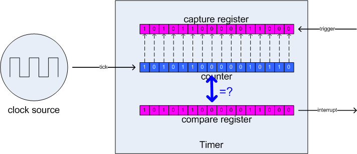
- capture registers copy the value of the counter when somethings triggers them. Typically, your application configures the timer such that the capture register records the time when an external pin toggles.
In the image below, the counter is at value b1010110000010110=0xac16=44054. The compare register it at value b1010110000011000=0xac18=44056, i.e. it will generate an interrupt in 2 ticks. The capture register is at value b1010110000010100=0xac14=44052, i.e. a trigger caused the register to capture the counter's value 2 ticks ago.
- Microcontrollers can contain multiple, independent timers, with multiple capture and multiple compare registers each. Since they are independent, each timer can be clocked from a different source, and can be used in a different mode.
- The counter can be configured to count in different modes (up, down, up/down, continuous, etc). See your counter's specific behavior in your microntroller's datasheet.
- The timer can interrupt the microcontroller on many different events: the counter reaches the maximum value, the counter rolled over, etc. See your microntroller's datasheet.
Requirements
On the clock source
Speed. The synchronization accuracy depends on the speed at which the counter in your timer increments. A timer timestamps events within a clock tick. If your timer is clocked by a 32kHz crystal, the event you timestamp will fall somewhere within a 30us window. The faster your clock, the more accurate the timestamp.
Synchronization accuracy depends entirely on:
- the sender's ability to sent a packet at a precise time in the slot (TsTxOffset);
- the receiver's ability to timestamp the reception of that packet.
With a 32kHz crystal, both these events will be at most 30us off; so your synchronization will be at most 60us off. This should be easy to see on a scope:
Drift. As detailed in TschSynchronization, a mote can spend tens of seconds without communicating, giving it lots of time to drift off and potentially desynchronize from your network. It is therefore important to have a clock source with a very consistent speed.
Given those two constraints, one typically uses a 32kHz crystal as the time clock source. This yields a timestamp accuracy of 30us while maintaining a small drift (10ppm is typical). Moreover, since that clock needs to run all the time, its a very energy-efficient solution.
On the counter
The width of the counter (i.e. the number of bits it contains) specifies the maximum duration is can count up. For the IEEE802.15.4e implementation, we need it to be able to count a slot length. With a 10ms slot and counter clocked by a 32kHz crystal, the counter needs to count up to 328.
We also need the counter to be able to count to a certain value, then roll over and generate an interrupt.
on the capture/compare registers
For the IEEE802.15.4e implementation, we need 1 compare register and 1 capture register.
OpenWSN implementation
Take a look at the source files lister above. The OpenWSN implementation dedicates a timer to IEEE802.15.4e. This timer is configured as follows:
- the clock source is a 32kHz external crystal;
- the counter is set up to count "up" between 0 and 328, and interrupt the microcontroller when it roll over to 0;
- a single capture register is used to timestamp the start/end of every packet sent/received. These events indicated in the state machine;
- a single compare register is used to time the different durations happening inside a slot, the value of which are defined in TschFsm#Defines.
Every time the timer rolls over, TschFsm#ti1 (or TschFsm#ri1 which are the same) is executed. Part of their execution is to configure the compare register. When the counter reaches the value of the compare register, another activity of the state machine gets executed. A state variable is kept in the IEEE802.15.4e implementation to associate a compare interrupt which a particular activity.
